|
| ArchiSITE |
TECH
TIPS
|
 |
|
 |
|
|
|
 |
|
What ways are there to define a terrain model? |
|
| You
can get data from files of different types, and you can define
the surface manually as well.
You
can open DXF files, text files with coordinate
triplets describing the surface with 3D points. XYZ file
contains coordinate triplets with line numbers.
ProSITE
builds the surface from these data.
You
can define the surface manually using the 3D Point Entry
tool, any of the Contour Line Entry tools and the
Ridge Line tool. The Ridge Line tool can also be used
to give contours.
[ Top of page ]
|
|
|
|
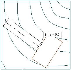
When entering 3D Points, what is the right order to type in
XYZ co-ordinates ?
|
|
| First,
specify the elevation (Z value) as it gets highlighted in the
co-ordinate box when choosing 3D Point tool. Now, you can just
click the locations of the same Z elevation. Or you can type the
X and Y co-ordinates manually, pressing Enter at the end of each
co-ordinate pair.
[ Top of page ]
|
|
|
|
What is the quickest way to create a surface model from a DXF
file which contains the contour lines of the site as 3D polylines?
|
|
| Choose
the Open command on the File menu. Select DXF on the File Type
drop down menu. Open the DXF with the polylines in it. When ProSITE
asks you whether to import 3D data from file, click "yes". Polylines
of the DXF are imported as contour lines. Specify the boundary
and issue the Build Surface command to calculate the terrain model.
[ Top of page ]
|
|
|
|
What unit does the DXF read in to ProSITE? |
|
| DXF
reads in according to the current unit set in the Options/Preferences/Drawing
Units dialog box. Therefore, be sure to set the right unit in
this dialog before reading the DXF file in.
[ Top of page ]
|
|
|
|
Can I define a surface with contours? |
|
| Yes,
in three ways.
1.
With the 3D Point Entry tool you can define several points
of the surface. It is advised to open a TIFF file, if any, as
a template so that you can trace easily.
This
method is suggested if you start a new surface.
2.
With the Contour Line tool you can define the known height
levels of the surface. It is advised to open a TIFF file, if
any, as a template so that you can trace easily.
This
method is suggested if you start a new surface, especially if
you have a sketch of the site based on a survey.
You
can also import DXF files containing 3D property elements -
either 3D points or lines, splines. ProSITE can calculate the
surface based on the 3D data of the input file, converting the
elements into 3D points and Contours.
DXF
files with just 2D data can be read and Contour lines can be
converted from its lines, splines, polylines.
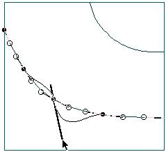
3.
With the Ridge Line tool you can define a ridge (many
points on the same height) similarly to a contour. Using the
Ridge Line tool start by defining the starting node's elevation
and click for its location (place the starting point of
the ridge line), enter the next elevation (if necessary) and
then just click to define the next node of an imaginary polyline
on a steady height.
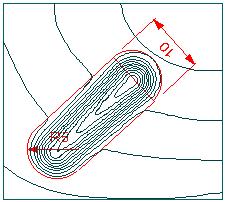
Before
defining the ridge lines set an Affect Range in the Surface
command on the Setting menu bigger than the distance between
the ridge lines (contours). This method is recommended if you
already have a surface model and want to modify it with defining
contours.
[ Top of page ]
|
|
|
|
How can I edit contour lines? |
|
There
are 3 ways to change a contour line:
- dragging
its node,
- adding
or removing its node,
- changing
its curve at a node by editing the tangent vector of the curve
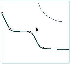
1. Dragging
node of a contour line
Select
the contour line. Place the cursor over its node. Press the mouse
button when the cursor snaps to the node. Drag the node from its
location with the mouse button pressed. (You can release the mouse
button later, as dragging.) Click to define the new location of
the node.
|
|
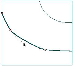
2. Adding and removing node
Select
the contour line.
|
|
| Place
the cursor over its node to be removed and CTRL - click when the
cursor snaps to the node. |
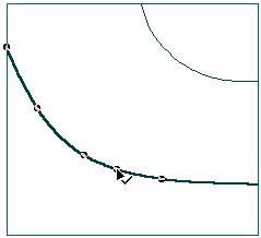
If
you want to add a new node, CTRL - click to define the location
of the new node. |
|
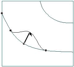
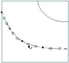
3. Changing curve of the contour line
Select the contour line. Press CTRL - Shift key combination. Tangent
vectors of the nodes appear as unfilled dots. Drag the tangent
vector of a node to change curve of contour.
|
|
|
|
|
|
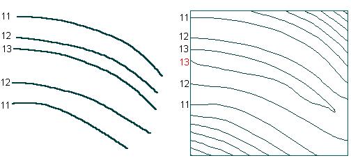
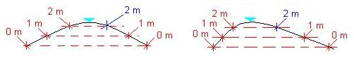
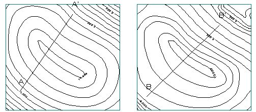
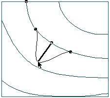
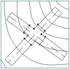
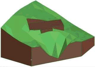
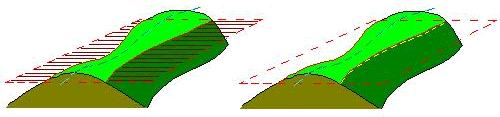
Contours
are closed curves by definition. A ridge line (as its name indicates)
cannot fulfill this requirement since a horizontal line has no
horizontal extension. Thus, it is impossible to specify a ridge
or ditch by contour line.
(See illustration
below)
As one
can see, the horizontal flat cut - indicated with red -
crosses the surface twice, which means two contour lines - indicated
with yellow dashed lines.
|
|
 |
|
|
|
|
|
If you
want to specify the series of the highest or lowest points, we
suggest you use the Ridge Line tool. With the Ridge Line tool,
you can specify symmetric slope environment.
[ Top of page ]
|
|
|
|
I read in an older ESM file and contour lines are still crossing.
What is the matter?
|
|
Saved
ESM files store their parameters. Therefore, they read in as they
were saved.
To make
use of ProSITE's surface generating improvements, set the Number
of Mesh Lines value to at least 75 on the Options/Surface settings
dialog box, and choose the Better option on the Option/Plan View
dialog.
[ Top of page ]
|
|
|
|
I have a sketch of a site. What is the easiest way to create
the terrain model of it?
|
|
| You
can enter the data from the map manually if you know the coordinates
of the given points. However, generally it is easier to make a
TIFF file from the map by a scanner. The TIFF file can
be opened by the Open Template command on the File menu. Having
a template "under" your worksheet you can enter points or contours,
tracing them on the template.
[ Top of page ]
|
|
|
|
I have the contour lines drawn in ArchiCAD. Is there a way
to transfer them into ProSITE to create a terrain from?
|
|
| ArchiCAD-drawn
SLABS, LINES, POLYLINES, SPLINES and ARCS can be Copy-Pasted
into ProSITE. The pasted objects can be converted into contour
lines with the use of the 4th and 5th tool option of the Contour
tool.
[ Top of page ]
|
|
|
|
How can I modify the surface? |
|
| The
difference between the terms Create and Modify is that while creating
a new terrain has a global impact, modification does not affect
all the terrain model, just a specified area, preserving the rest.
Creating
a new model means the integration into a new model of all terrain
specific data (3D Points and Contour Lines), both the already
built-in and the recently specified ones. Since this new model
is calculated on a newly created database, the terrain may differ
from the previous model. Thus all the previously visible contours
that are the representation of the surface model may be altered
Modifying
a model means leaving the database untouched, which ensures
the preservation of the model, while allowing changes to take
place in a defined affect zone around the modification (in a
distance or within a given polygon).
There
are 5 methods to modify an existing surface.
1. Modifying
the height of any location
In this
case you can specify a polygon within which the changes impact
the surface.
You
can do this with the Scan Label tool. After choosing
the Scan Label tool move the cursor to the location whose elevation
you want to change, click or press Z and enter the new z value.
Press the Enter button and choose Build Surface from
the Edit menu. ProSITE recalculates the surface and the new
elevation will take effect.
2. Modifying
the height of existing 3D points
You
can do it with the Scan Label tool. After choosing the
Scan Label tool move the cursor on the existing 3D Point whose
elevation you want to change, click or press Z and enter the
new z value. Press the Enter button and choose Build Surface
from the Edit menu. ProSITE recalculates the surface within
the preset Affect Range Radius and the new elevation will take
effect.
3. Modifying
the height level of an existing Contour Line
You
can do this with the Scan Label tool. After choosing
the Scan Label tool move the cursor on the existing Contour
Line whose elevation you want to change, click or press Z and
enter the new z value. Press the Enter button and choose Build
Surface from the Edit menu. ProSITE recalculates the surface
within the preset Affect Range Radius and the new elevation
will take effect.
4. Editing
Contour Lines
You
can do this with the Arrow/Selection tool.
Select
the Contour Line whose curve you want to edit. Movable Selection
Nodes appear. Drag the Nodes to the desired place to change
the curve.
You
can also modify the curve of contours by editing their Nodes'
Normal Vectors. Press Ctrl - Shift and the Normal Vectors of
the selected contour(s) appear. Drag its end nodes to change
the curve.
Choose
Build Surface from the Edit menu. ProSITE recalculates
the surface within the preset Affect Range Radius and the new
elevation will take effect.
5. Placing
Ridge or Ditch
With
the Ridge Line tool you can define a ridge or ditch (many
points on the same or different height).
Using
the Ridge Line tool start by defining the starting node's elevation
and click for its location (place the starting point of
the ridge line), enter the next elevation (if necessary) and
then just click to define the next node of an imaginary polyline
on a steady height.
Choose
Build Surface from the Edit menu. ProSITE recalculates
the surface within the preset Affect Range Radius and the new
elevation will take effect.
NOTE
that Placing new 3D Points or Contour Lines are not among the
list of Terrain Modification. These actions Create new surface!
[ Top of page ]
|
|
|
|
When does Affect Range take effect? |
|
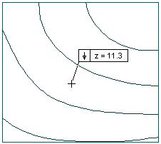
Affect
range is the distance that closes the area where surface modifications
take effect.
There
are 3 cases when Affect Range effects surface recalculation:
- modifying
the surface by changing the height of a surface location with
the help of the Scan Label tool,
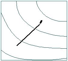
- modifying
the surface with the Ridge Line tool,
- modifying
Contour line.
The
Affect Range in the different cases is as follows:
1. Changing
height of a surface location
|
|
2. Modifying
the surface with the Ridge Line tool
|
|
3. Modifying
Contour line
|
|
|
|
|
|
[ Top of page ]
|
|
|
|
What does Affect Range depend on? |
|
| Affect
Range is an independent explicit value, that is set in the Options/Surface
setting dialog box. Its value is understood in the unit specified
in the Options/Preferences/Drawing Units dialog box.
[ Top of page ]
|
|
|
|
Can I modify the elevation of a house plot or plateau? |
|
| Yes,
you can do this with the Scan Label tool. After choosing
the Scan Label tool move the cursor over the house plot (or plateau)
whose elevation you want to change. Click or press Z and enter
the new Z value. Pressing Enter, the new elevation will take effect
immediately, without using the Build Surface command.
[ Top of page ]
|
|
|
|
Why does the earth balance disappear after some steps? |
|
| If
you change the surface, the previously counted earth balance is
not valid. Therefore ProSITE hides it. You can get the current
earth balance whenever you like, by clicking the Earth balance
button.
[ Top of page ]
|
|
|
|
Can I reset the basic value for earth balance? |
|
Yes,
click the " V=0"
next to the Earth balance button. V=0"
next to the Earth balance button.
[ Top of page ]
|
|
|
|
What unit is the earth balance displayed in? |
|
| Earth
Balance is always displayed in metric unit, namely cubic meter.
[ Top of page ]
|
|
|
|
Is there an autosave feature in ProSITE? |
|
| Yes.
It works automatically after every 20 steps. The AutoSave
file (Autosave.ASQ) can be opened only with ProSITE, it does
not contain the necessary information to open it using ArchiCAD.
[ Top of page ]
|
|
|
|
How can I draw a house plot exactly for a building whose model
I already have in ArchiCAD?
|
|
| ArchiCAD
drawn SLABS and LINES, POLYLINES, SPLINES, ARCS can be Copy-Pasted
into ProSITE. The pasted objects will help you define the exact
house plot for the building.
[ Top of page ]
|
|
|
|
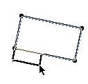
How can I edit a house plot or any other object? |
|
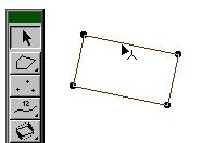
To
edit an object, such as the boundary, a houseplot or a plateau,
it has to be selected first.
Select
the object by simply clicking on it if you are using the Arrow
tool, or Shift - Click if you are using any other tool. (Only
one object can be selected to modify.)
|
|
 |
|
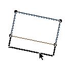
With the
mouse button pressed, drag the node or the edge you want to relocate.
Release
the mouse button and click to place the node or edge at the desired
location.
|
|
dragging
an edge, dragging a
node |
|
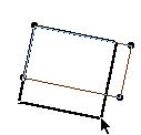
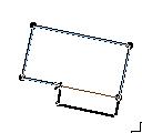
It is
also possible to add a new node.
Select
the object. CTRL-Click on the edge, where the new node has to
be inserted. With the mouse button pressed, drag the node just
created.
You can
toggle which side of the object to be modified by the new node
by pressing the CTRL key.
|
|
|
|
|
|
Release
the mouse button and click to place the new node at the desired
location.
Nodes
can be removed from the selected object in the same way, by
CTRL-Clicking on them.
However,
one cannot reduce the number of nodes to less than the minimum
which is 4 in case of perpendicular and 3 in case of arbitrary
objects.
The
object preserves its perpendicular or arbitrary property after
adding or removing nodes of an object.
[ Top of page ]
|
|
|
|
How can I set different angles for the slopes of a plateau? |
|
You
can set different angles for the slopes either when creating the
plateau, or any time later on.
1. Defining
slopes when creating the plateau
When finishing
the shape by closing the plateau, click on the edge whose slope
you want to set. The Changing Slope dialog box appears. Here,
you can set both slope parameters.
If you
want to change slopes of other edges as well, press OK, if you
have finished click Finish.
2. Redefining
slopes of existing plateaus
Select
the plateau whose slope you want to modify. Double click on the
plateau tool on the toolbox to make Plateau Settings dialog box
appear. Click the Change Slope button. Click the edge whose slope
you want to set. The Changing Slope dialog box appears. Here,
you can set both slope parameters. If you want to change slopes
of other edges as well, press OK, if you have finished click Finish.
[ Top of page ]
|
|
|
|
Can I copy site features in ProSITE? |
|
| Yes,
house plots and plateaus can be Copy-Pasted within ProSITE.
[ Top of page ]
|
|
|
|
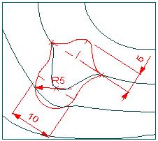
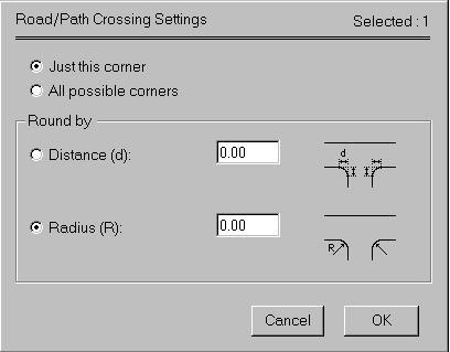
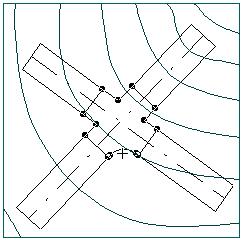
How can I round the edge of a crossing? |
|
First
the Road tool has to be chosen, then select the crossing.
The easiest
way to select the crossing rather than the road is Shift-Clicking
on the common line of the crossing and the actual segment.
|
|
Click
on the edge you want to round.
|
|
The Crossing
settings dialog appears, where you can specify the parameters
of the rounding.
|
|
If you
choose "Just this corner" then just that edge will be rounded
which was clicked on in the previous step.
If you
choose "All possible corners" then all the edges of the selected
crossing will be rounded.
You
can define the parameter of the rounding either by its radius
or its length.
Click
OK to finish.
|
|
 |
|
 |
|
|